Locking in vnmr
From NMR Wiki
Contents |
What is "lock"
Lock (or more precisely - field frequency lock) is used to control magnetic field in the sample so that the resonance frequencies do not drift.
Field of the superconducting magnet is slowly changing. Even though this change is usually very small, it considerably deteriorates quality of the data. In Varian systems lock channel is usually tuned to the resonance frequency of deuterium. When that frequency it is changing, a compensating current is added to the Z0 room temperature shim coil so that the original value of the frequency is restored.
All other frequencies used in the experiments (e.g. 1H, 13C etc.) are "tied" to the frequency of the lock channel.
Manual locking
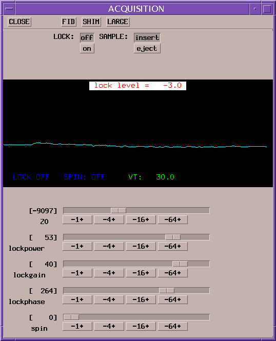
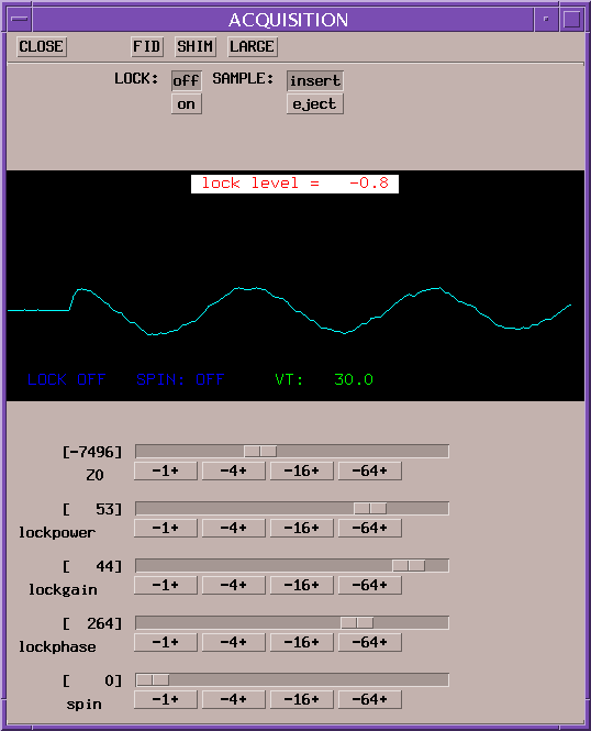
Below that data panel, there are five controls: "Z0", "lockpower", "lockgain", "lockphase" and "spin". Above label for each control in brackets it's current value is shown. Each control has a slider bar, draggable with the mouse; also there are four buttons ("+1-" and so on). While the slider bar allows easy approximate adjustment of the control's value, buttons allow setting that value precisely. Left-clicking a button will substract a corresponding value, right-clicking will add that value.
Note: lock level shown here is low - lock power or gain might be increased in this case. However a trained operator may not need that as he/she can also notice that there is measurable signal and the lock frequency is fairly close to zero. A small further adjustment of "Z0" and then perhaps some adjustment of "lockphase" might complete the procedure.
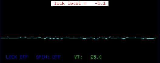
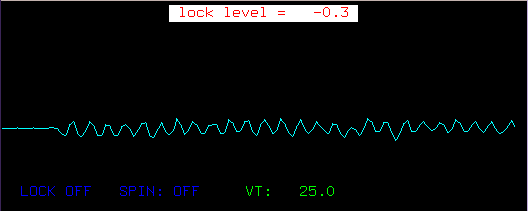
Manual locking in vnmr is controlled via 'Acqi' window. To get there - type 'acqi' in the command line or click 'Acqi' button. A window as shown on Fig. 1 will open. Now click "Lock" button. The window will probably change into something like you can see on Figure 2 or 3. - assuming that lock is not yet well tuned. Turn lock off by clicking "off" button.
Lock picture
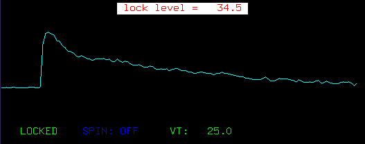
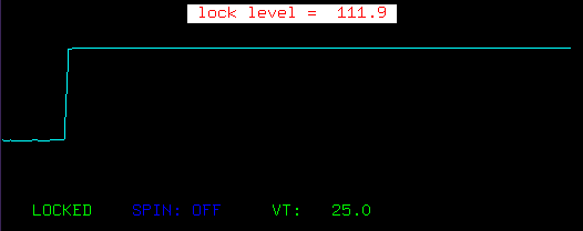
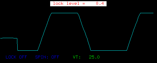
The curve that you see in the window with the black background is an FID (free induction decay) of the lock nucleus. Ideally, frequency of the lock channel transmitter should be set exactly at the larmor frequency of that nucleus. If that condition is met then frequency of FID will be exactly zero, also phase of the FID is adjusted so that it is shown as a cosine wave (with its maximum positive value at the very beginning). So ideal lock picture will look like a perfect step (a fraction of a very long cosine wave cut at its beginning need a picture of good lock) Lock level is weak in Figure 2., while in Figure 3 lock frequency is somewhat off. If lock signal is perfectly flat - (i.e looks like straight flat line) - either Z0 is misset (this section will help you fix that) or something else is wrong.
Acqi lock controls
Legend of Figure 2 explains how to manipulate the lock contorls. "Z0" - sets amount of current sent into the zero order field gradient shim coil which simply adds constant magnetic field in the direction of the magnet axis. This coil allows to match larmor frequency of the lock nucleus to the lock channel frequency. "Lockpower" sets amount of power applied to the lock channel. "Lockgain" sets amplifier gain level of the lock channel receiver. "Lockphase" sets phase of lock channel transmitter signal. "Spin" sets frequency of sample spinning (not relevant to locking)
Locking procedure
First adjust lock power and gain so that you see some sort of wave in the data panel (similar to Fig. 3). Then start changing value of "Z0" so that frequency of that wave is minimal. You need to pay attention to frequency, not maximum height of wave at this stage. However, if the wave is too weak for you to make judgement about the FID frequency (like on Figure 2) - increase power or gain, if it is too strong (i.e. wave is clipping at the extremes) - decrease lock gain or power. Which one - lock power or gain should be adjusted? To some extent it does not matter, however too much power can lead to some artefacts with the lock channel (see section on lock troubleshooting).
When lock signal starts looking like step function, keep adjusting "Z0" with "-1+" button - the finest control - until height of the step is at maximum. If height exceeds 100% (clips) on top, lock power or gain should be decreased, then you can continue with the fine "Z0" adjustment.
Finally, adjust lock phase to the maximum level and turn lock on by clicking "on" button. Lock level should stay stable when lock turns on. If lock level jumps when turned on/off - either lock power is too high or "Z0"/"lockphase" are still not well adjusted.
Lock troubleshooting
The following table might help you resolve problem with locking, please add more to this table.
| symptom | possible solution |
| lock level jumps up and down | lock power too high - lower it and possibly increase lock gain |
| lock level jumps when lock is turned on/off |
|
| lock level is flat zero |
|
| lock level is still zero - no matter how "Z0", "lockpower" and "lockgain" are adjusted |
|
| at the very best lock signal looks like stooping roof not ideal flat step function: |
|
| Lock picture looks like sawtooth: | Z0 needs adjustment so that frequency of oscillation becomes as small as possilbe.
|
| Looks like a flat step, but lock level is > 100%, i.e. signal is clipped at top |
|
| Lock wave is clipped |
|
Categories: Vnmr tutorials | Fixme | User guides | Vnmr

